


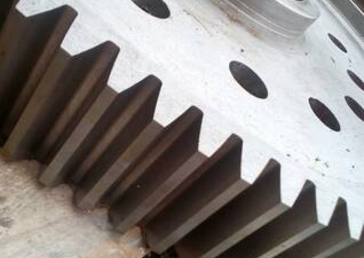

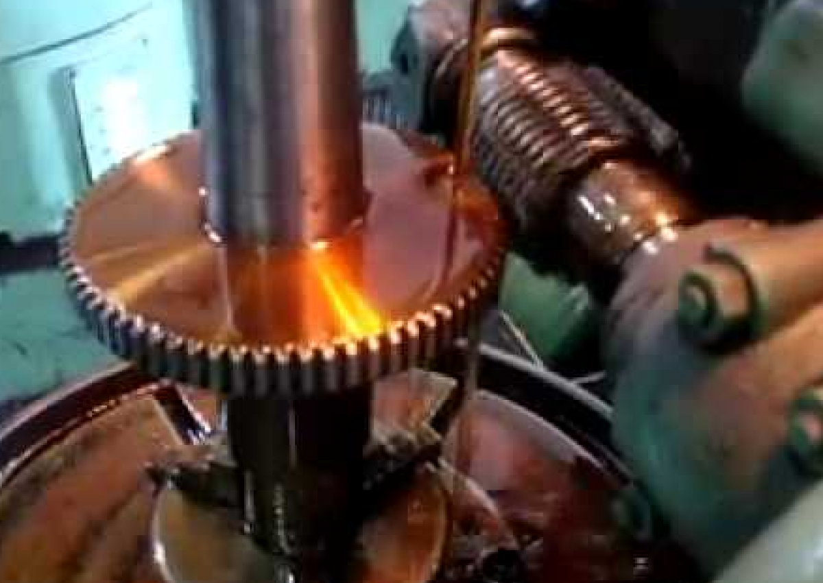
Gear hobbing
 We deal with external tooth cutting. We make gears of different diameters.
Max. Processing diameter 500mm.
Max. Tooth length 300mm.
Max. Part length 1500mm
Max.room module 10.
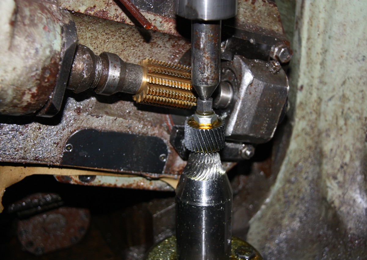
It is not so rare in industry that it is necessary to cut helical and helical gears with an undeclared number of teeth on a particular gear cutting machine. These are basically the so - called "Prime" numbers: 101 - 103 - 107 - 109 - 113 - 121 - 123, etc. In order to cut these teeth, it is necessary to introduce additional adjustment of the guitar differentials with a complicated and not completely clear adjustment procedure for an ordinary performer. and does not always provide an opportunity to reduce oneself.
We recommend an easier way based on the modified e: f value and using the program up to
"Calculation of High Precision Guitar Differentials"
Example of machine 5K328A:
With the number of teeth cut Tolerance
Z = 101 Guitar division: 30 × 43/95 × 89 at e: f = 61:47 ∆ = 00 00 '00 "!
Z = 103 Guitar division: 41 × 67/100 × 65 at e: f = 34:74 ∆ = 00 00 '00 "!
Z = 107 Guitar division: 00 × 00/00 × 00 at e: f = 00:00 ∆ = 00 00 '00 "!
Z = 109 Guitar division: 43 × 89/100 × 100 at e: f = 35:73 ∆ = 00 00 '55 "!
Z = 113 Guitar division: 23 × 59/98 × 70 at e: f = 51:57 ∆ = 00 00 '00 "!
Z = 121 Guitar division: 35 × 40/62 × 55 at e: f = 31:77 ∆ = 00 00 '00 "!
Z = 123 Guitar division: 30 × 40/90 × 41 at e: f = 36:72 ∆ = 00 00 '00 "!
The angular error ∆ for gears with M6 module and the recommended feed rate for this machining of 2.46 mm per part revolution is on average no more than 1 arc minute !!!, which is several times less than the permissible values for gears in accuracy class 8.
Guitar sections, in fact, including and after cutting A simple number of teeth are represented in addition to the program: "Calculation of guitar differentials for any gear cutting machine with ultra-high selection gear wheel"
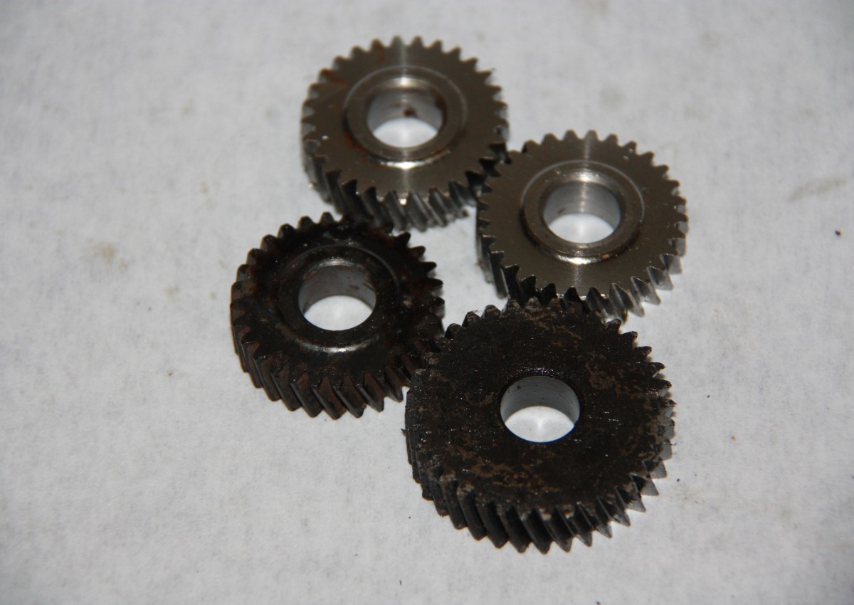
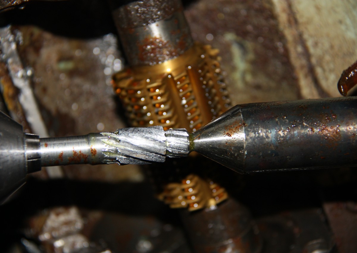
In the event of damage to the gear or gears in the gearbox of a machine or machine, it becomes necessary to use the "old" part and sometimes a drawing of the debris fragments must be made to make a new wheel and / or gearbox. This article will be useful for those ...
... which need to restore gears without working drawings for broken parts.
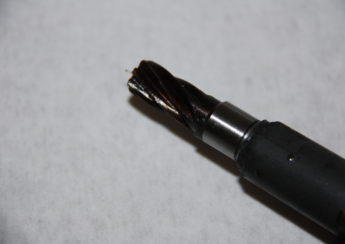
Generally, for a lathe and a cutter, all the required dimensions can be obtained using caliper measurements. For those who need more attention, the so-called mating dimensions - the dimensions that determine the connection to other parts of the unit - can be determined by the diameter of the shaft to which the wheel is attached and the size of the shaft wrench or axle wrench. With the parameters, the situation is more complicated for the hobbit operator. In this article, we will not only define the gearbox module, I will try to outline a general procedure for determining the main parameters of all gear discs based on the results of measurements of worn gear and wheel samples.
We "arm ourselves" with a caliper, a goniometer or at least a garage, a ruler and MS Excel, which will help to quickly perform the usual and sometimes complicated calculations, and we get to work.
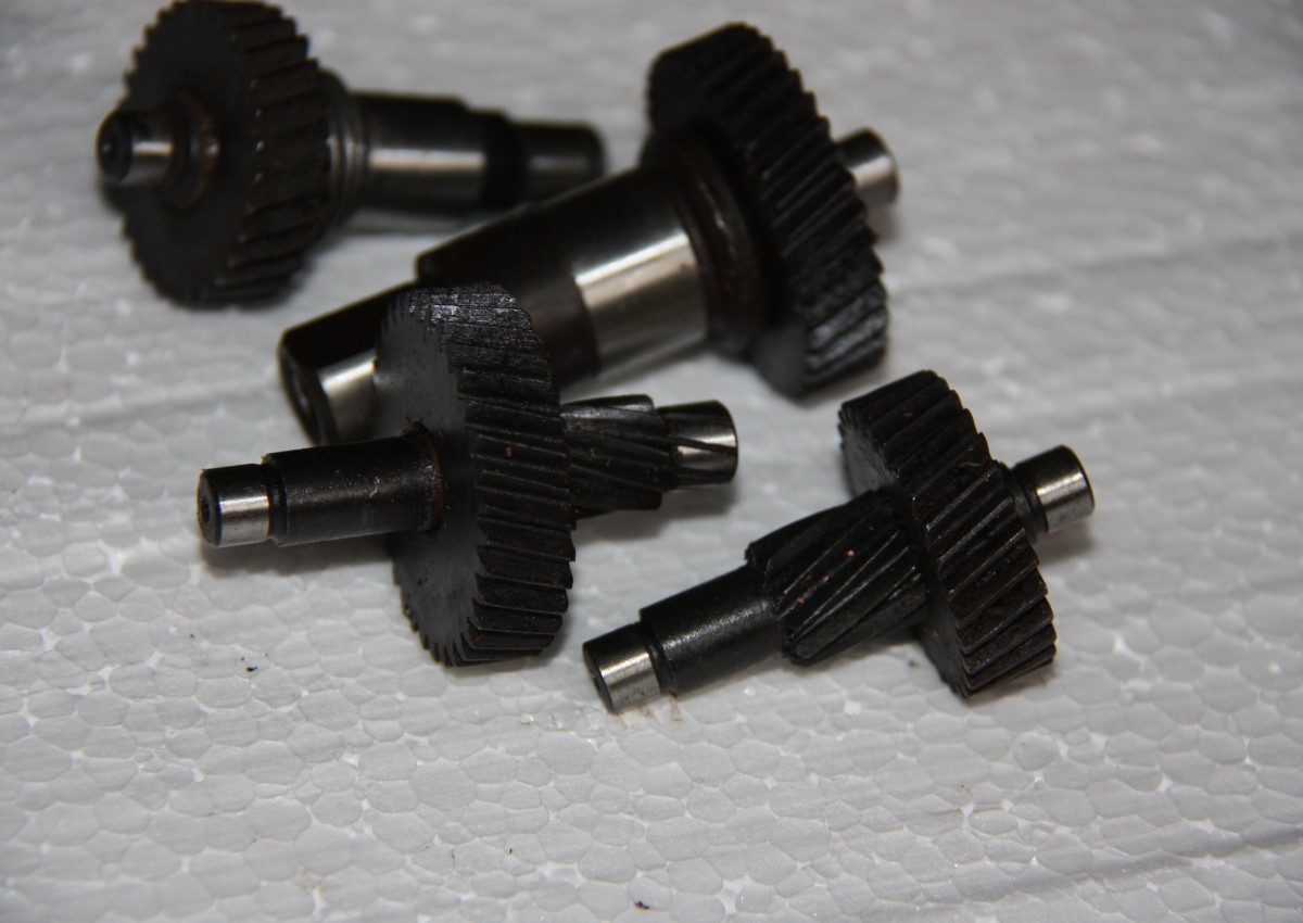
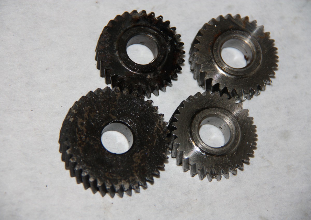
As usual, I will look at this topic with examples, for which we first consider a cylindrical guide gear with an external gear and then a helical gear .
Several articles are devoted to calculation tools on this site: " Calculation of the tool ", " Calculation of geometry of the tool ", " Calculation of the duration of the total normal for the tool ". These are illustrations with the notation of the parameters used in this article. This article continues the topic and is intended to reveal the operation of algorithms during repair and refurbishment work, that is, work that is the opposite of design work.
Calculations can be performed in MS Excel or OOo Calc from the Open Office package.
The Excel worksheet cell formatting rules that are applied to this blog's articles can be found on the page " on the blog ."
Calculation of gearbox wheel and gearbox parameters.
Initially, we assume that the gear and the gear have uncleaned tooth profiles and were manufactured with the parameters of the initial contour in accordance with GOST 13755-81. This GOST regulates the three main (for our task) initial contour parameters for modules larger than 1 mm. (If the modules are smaller than 1 mm, the initial contour is specified in GOST 9587-81; modules smaller than 1 mm are recommended for kinematic use only, ie not in power transmissions.)
Both gear and wheel measurements are required to correctly calculate the transmission parameters
We start filling in the Excel table with the parameters of the original contour.
 http://al-vo.ru/wp-content/uploads/2014/01/iskhodnyi-kontur-300x208.jpg 300w" sizes="(max-width: 476px) 100vw, 476px" >
1. Write the angle of the initial contour profile in α degrees
to cell D3: 20
2. Introduce room head height factor h a *
to cell D4: 1
3. Entered transmission radial clearance factor c *
to cell D5: 0.25
In the USSR and Russia, 90% of general mechanical engineering gears were manufactured with precisely the following parameters, which allowed the use of a single gear cutting tool. Of course, gears with Novikov gears were made and special original contours were used in the automotive industry, but most gears were designed and manufactured with a contour in accordance with GOST 13755-81.
4. Wheel tooth type (adhesion type) T write down
to cell D6: 1
T = 1 - with external teeth at the steering wheel
T = -1 - with internal teeth at the steering wheel (internal gear transmission)
5. Transmission from center to center a w mm measured along the gear housing and enters the value
to cell D7: 80.0
Several transmission centers are standardized. The measured value can be compared with the values given in the note to cell C7. The match is not mandatory, but very possible.
6.-9. Transmission parameters: number of teeth z 1 , diameters of tooth tips and valleys d a 1 and d f 1 mm, calculate the angle of inclination of the teeth on the surface in β a 1 degrees and measure with a vernier caliper and goniometer on the original sample and record accordingly
to cell D8: 16
to cell D9: 37.6
to cell D10: 28.7
to cell D11: 0.0
10-13. Wheel parameters: number of teeth z 2 , diameters d a 2 and d f 2 mmof tooth tips and valleys, theangle ofinclination of the teethon the tip cylinder β a 2 degrees is determined in the same way - according to the original wheel sample - and recorded accordingly.
to cell D12: 63
to cell D13: 130.3
to cell D14: 121.4
to cell D11: 0.0
Pay attention: the tooth inclination angles β a 1 and β a 2 are the angles measured on the cylindrical surfaces of the tooth tips !!!
We measure the diameter as accurately as possible! For wheels with the same number of teeth, this is easier if the nozzles are not stuck. For wheels with an odd number of teeth, when measuring, remember that the dimensions shown in the caliper are slightly smaller than the actual diameter of the protrusions !!! We make several measurements and, from our point of view, the most reliable values in the table.
 http://al-vo.ru/wp-content/uploads/2014/01/modul-zubchatogo-kolesa-1-182x300.jpg 182w" sizes="(max-width: 476px) 100vw, 476px" >
Calculation results:
14. The initial values of the gearbox shall be determined taking into account the dimensions of the gear m 1 and the gear wheel m 2 mm respectively.
in cell D17: = D9 / (D8 / COS (D20 / 180 * PI ()) + 2 * D4) = 2.089
m 1 = d a1 / ( z 1 / cos ( β 1 ) + 2 * ( h a * ))
and in cell D18: = D13 / (D12 / COS (D21 / 180 * PI ()) + 2 * D4) = 2.005
m 2 = d a2 / ( z 2 / cos ( β 2 ) + 2 * ( ha *))
The gearbox plays the role of a universal factor that determines both the size of the teeth and the overall dimensions of the wheel and gearbox.
We compare the values obtained with the values from a series of standard modules, the fragment of which is given in the note to cell C19.
The calculated values obtained are usually very close to one of the values in the standard series. We assume that the required modulus of the gear and gear m mm is equal to one of these values and enter it
to cell D19: 2000
15. The initial values at the inclination of the teeth of the head are determined from the results of the measurement tools in beta 1 and gear β 2 degrees, respectively.
in cell D20: = ASIN (D8 * D19 / D9 * TAN (D11 / 180 * PI ())) = 0.0000
β 1 = arcsin ( z 1 * m * yellow ( β a1 ) / d a1 )
and in cell D21: = ASIN (D12 * D19 / D13 * TAN (D15 / 180 * PI ())) = 0.0000
β 2 = arcsin ( z 2 * m * yellow ( β a2 ) / d a2 )
We assume that the desired angle of inclination of the teeth β in degrees is equal to the measured and recalculated values, and we record
per cell D22: 0.0000
16. Preliminary values of the compensating displacement coefficient are calculated from the measurement results of the gear Δy 1 and the gear Δy 2, respectively
in cell D23: = 2 * D4 + D5- (D9-D10) / (2 * D19) = 0.025
Δy 1 = 2 * ( h a * ) + ( c * ) - ( d a1 - d f1 ) / (2 * m )
and in cell D24: = 2 * D4 + D5- (D13-D14) / (2 * D19) = 0.025
Δy 2 = 2 * ( ha * ) + ( c * ) - ( d a 2 - df 2 ) / (2 * m )
We analyze the obtained calculated values and record the decision on the value of the smoothing displacement factor Δy
in cell D25: 0.025
17.18. The diameter diameters of gear d 1 and gearbox d 2 are calculated accordingly
in cell D26: = D19 * D8 / COS (D22 / 180 * PI ()) = 32,000
d 1 = m * z 1 / cos ( β )
and in cell D27: = D19 * D12 / COS (D22 / 180 * PI ()) = 126,000
d 2 = m * z 2 / cos ( β )
19. Pitch center distance a mm we calculate
in cell D28: = (D27 + D6 * D26) / 2 = 79,000
a = ( d 2 + T * d 1 ) / 2
20. We calculate theprofile angle α t in degrees
in cell D29: = ATAN (TAN (D3 / 180 * PI ()) / COS (D22 / 180 * PI ()) / PI () * 180 = 20.0000
α t = arktāns (tg ( α ) / cos ( β ))
21. The angle of engagement α in tw degrees is calculated
in cell D30: = ACOS (D28 * COS (D29 / 180 * PI ()) / D7) / PI () * 180 = 21.8831
αtw = arccos ( a * cos ( αt ) /aw )
 http://al-vo.ru/wp-content/uploads/2014/01/smeshchenie-iskhodnogo-kontura-300x201.jpg 300w" sizes="(max-width: 476px) 100vw, 476px" >
22.23. The displacement coefficients of gear x 1 and wheel x 2 are determined respectively
in cell D31: = (D9-D26) / (2 * D19) -D4 + D25 = 0.425
x 1 = ( da 1 - d 1 ) / (2 * m ) - ( ha * ) + Δy
and in cell D32: = (D13-D27) / (2 * D19) -D4 + D25 = 0.100
x 2 = ( da 2 - d 1 ) / (2 * m ) - ( ha * ) + Δy
24.25. The coefficient of deviation sum (difference) x Σ (d) is calculated to check the correctness of the previous calculations using two formulas respectively
in cell D33: = D31 + D6 * D32 = 0.525
x Σ (d) = x 1 + T * x2
un šūnā D34: = (D12 + D6 * D8) * ((TAN (D30 / 180 * PI ()) - (D30 / 180 * PI ()))) - (TAN (D29 / 180 * PI ())) - ( D29 / 180 * PI ()))) / (2 * TAN (D3 / 180 * PI ())) = 0,523
x Σ ( d ) = ( z 2 + T * z 1 ) * ( inv ( α tw ) - inv ( α t )) / (2 * tg ( α ))
The values calculated using different formulas differ very little! We believe that the values of the gear and gear module as well as the displacement coefficients found are correct!
Calculation of helical gear wheel and transmission parameters.
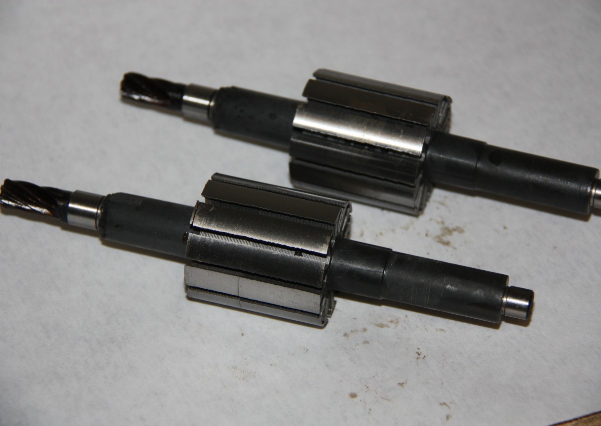
Let's move on to the example of a helical gear and repeat all the steps we performed in the previous section.
It is almost very difficult to measure the angle of inclination of the teeth with the required accuracy using a proractor or proractor. Usually I rolled the wheel and gear onto a sheet of paper and then, using prints with a drawing board dividing head proractor, I made initial measurements with a degree or greater accuracy ... In the example below, I measured: β a 1 = 19 ° and β a 2 = 17.5 °.
Once again, I draw your attention to the fact that the angle of inclination of the teeth on the vertices β a 1 and β a 2 in the cylinder is not the angle β , which is involved in all basic transmission calculations !!! The angle β is the angle of inclination of the teeth on the step cylinder (for transmission without displacement).
 http://al-vo.ru/wp-content/uploads/2014/01/modul-zubchatogo-kolesa-2a-182x300.jpg 182w" sizes="(max-width: 476px) 100vw, 476px" >
Given the small values of the calculated displacement coefficients, it is useful to assume that the transmission was performed without gear and displacement of the gears and gearbox generating circuits.
Let's use Excel service "Parameter selection". I wrote here in detail and with pictures about this service.
From the main Excel menu, select "Service" - "Parameter Selection" and fill in this window:
Set in cell: $ D $ 33
Value: 0
Changing cell value: USD D $ 22
And click OK.
We get the result β = 17.1462 °, x Σ ( d ) = 0, x 1 = 0.003≈0, x 2 = -0.003≈0!
 http://al-vo.ru/wp-content/uploads/2014/01/modul-zubchatogo-kolesa-2b-182x300.jpg 182w" sizes="(max-width: 476px) 100vw, 476px" >
The transmission was most likely done without the displacement, the gearbox and the gear module, as well as the angle of the teeth, we have determined you can make drawings!
Important notes.
The initial contour offset when turning the teeth is used to restore worn wheel tooth surfaces, reduce the penetration depth on the gear shafts, increase the load capacity of the gearbox, perform a transmission with a specified center distance equal to the step distance to reduce the gear foot and tooth tip reduction. wheels with internal teeth.
Distinguish between height correction ( x Σ ( d ) = 0 ) and angular ( x Σ ( d ) ≠ 0 ).
In practice, generating circuit displacement is commonly used in the production of vortex gears and very rarely helical gears. This is due to the fact that, due to the bending strength, an oblique tooth is stronger than a straight tooth, and the required center distance can be provided by an appropriate tooth angle. If height correction is rarely used for helical gears, then angle correction is almost never used.
The helical gear runs smoother and smoother than the gearbox. As already mentioned, oblique teeth have a higher bending strength, and the specified center distance can be provided by the angle of inclination of the teeth without using the displacement of the generating circuit. However, in gear units with helical teeth, additional axial loads appear on the shaft bearings and the wheel diameters are larger than bevel gears with the same number of teeth and modulus. The production of helical gears is less efficient, especially wheels with internal teeth